Getting Started With DeZign for Databases
Table of contents:- 1. Creating a new data model
- 2. Adding a new entity
- 3. Adding a relationship
- 4. Using domains
- 5. Generating a new database
- 6. Synchronizing your model with the database
- 7. Generating documentation
- 8. Adapting diagram presentation
DeZign for Databases is a database design and modeling tool. This getting started document is a short introduction to start data modeling with DeZign for Databases. It explains how to create a new data model, create the first entities in your ERD (ER Diagram) and connect them by relationships.
Creating a New Data Model
You can start a new project in two ways:
1. Import an Existing Database
To import an existing database select File | Import database | [DATABASE TYPE] | [DATABASE VERSION] | Import from database or Import from SQL file from the menu.
If you choose to import from database you need to enter the database connection parameters (like database name, username, password,..). If your database supports schemas or owners, you may provide a single schema/owner to only import that schema/owner. If you leave it empty all objects from all schemas/owners will be imported. After importing all entities will be placed on the main diagram. If multiple schemas are imported then a subdiagram is made for each individual schema you import.
2. Create a New Model From Scratch
To create a new model from scratch select File | New project. The New project dialog appears where you must choose the database type (Oracle, MS SQL Server, MySQL, PostgreSQL, ..). After pressing OK DeZign for Databases opens the main diagram where we can start to add database objects such as entities and relationships.
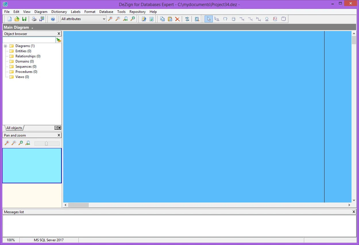
Figure 1: Empty work area after creating a new project.
In the left upper part you see the Object Browser where you see a folder for each type of database object:
- Entities (tables in the database)
- Relationships (foreign keys in the database)
- Domains
- Sequences
- Procedures
- Views
Adding a New Entity
We assume that we started a new project from scratch. Now we start by adding a new entity to the diagram. You can add a new entity by clicking the Insert Entity button on the drawing tools pane (see Figure 2). The button will be down and you can click in the diagram at the location where you want the entity to be positioned. You can also select Dictionary | New entity (shortcut: Ctrl-E). Now the Edit entity dialog appears. Provide a name like Customers in the Entity name field on the General tab and move on to the Attributes tab.
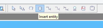
Figure 2: Insert Entity Button.
Adding Attributes
You can add a new attribute by clicking on the Add attribute button (see Figure 3) at the top on the right of the Attributes tab (shortcut: Ctrl-Insert).
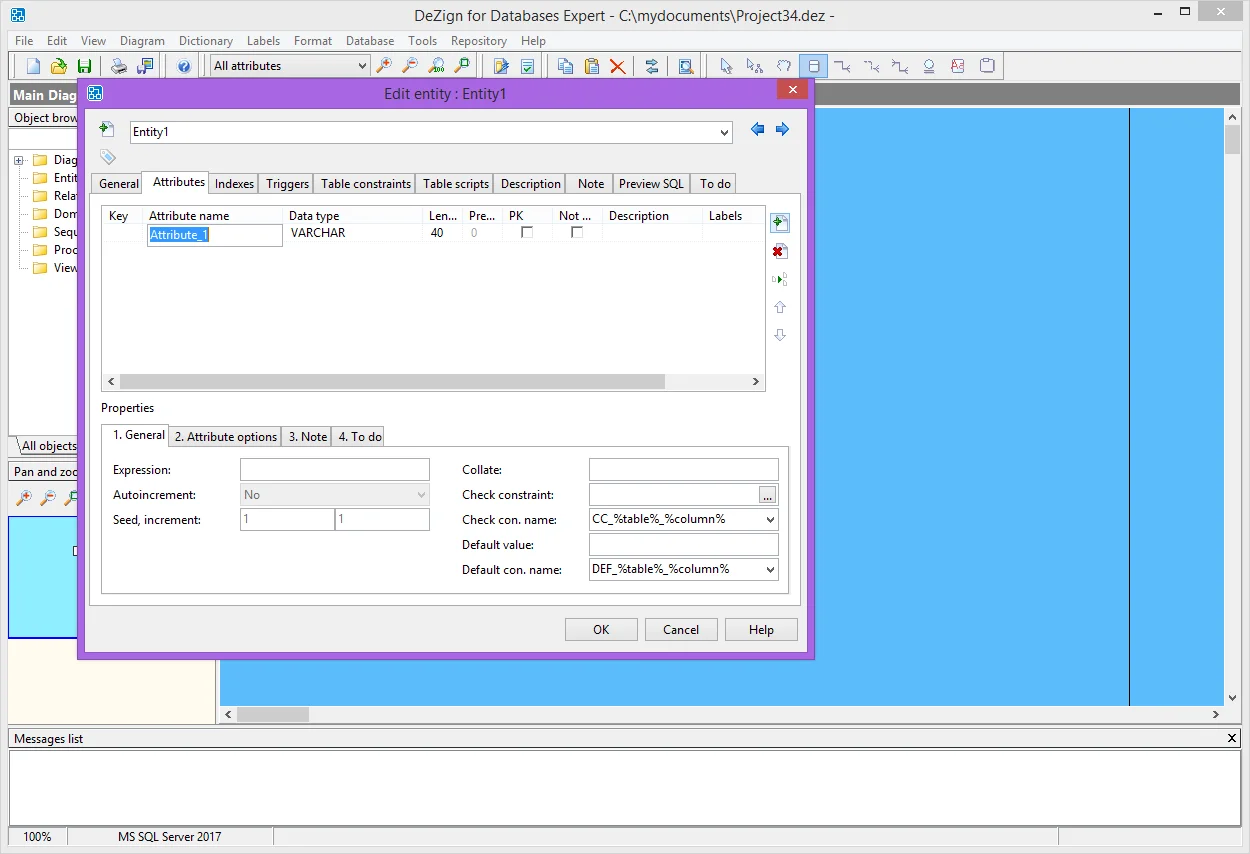
Figure 3: Entity dialog tab "Attributes".
You can enter the general properties of the attribute like name, data type etc. At the bottom you see additional properties like check constraint and default constraint. It depends on the database type and data type which properties are displayed. Let's add the following attributes:
- CustomerID, VARCHAR2(10), PK.
- CompanyName, VARCHAR2(50), Not null.
- ContactName, VARCHAR2(50).
- Email, VARCHAR2(50).
- Phone, VARCHAR2(25).
- Address1, VARCHAR2(50), Not null.
- Address2, VARCHAR2(50).
- Country, VARCHAR2(50), Not null.
Adding a Relationship
For a Customer there may be any number of Orders. We will create an entity Orders that has a relationship with the Customers entity. Create a new entity Orders and add the following attributes:
- OrderID, VARCHAR2(10), PK.
- CustomerOrderNumber, VARCHAR2(50)
- OrderDate, Date, Not null.
- ShippedDate, Date.
- ShipAddress1, VARCHAR2(50), Not null.
- ShipAddress2, VARCHAR2(50).
- ShipCountry, VARCHAR2(50), Not null.
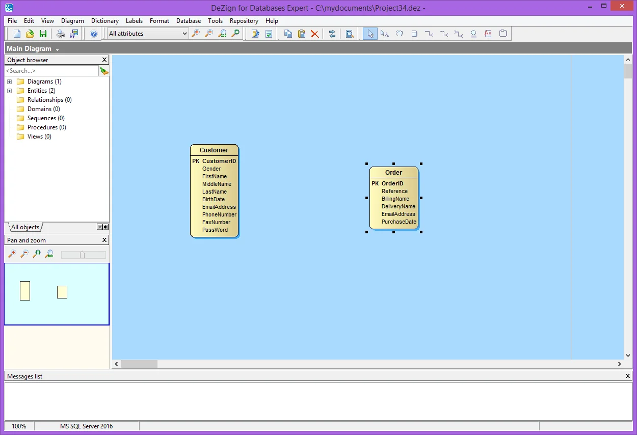
Figure 4: Situation before adding the relationship.
Now we will add a relationship. Click on the Insert Non-Identifying Relationship button (see Figure 5) in the toolbar. Position the mouse over the Customers entity, drag the mouse to the Orders entity and release the mouse button. Next, double click on the relationship and check "Mandatory parent" to make sure that an Order is always assigned to a Customer. Note that you can also create a relationship without using the Drawing tools by selecting Dictionary | New relationship (shortcut: Ctrl-R) from the menu.
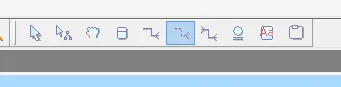
Figure 5: Insert Non-Identifying Relationship button.
We just created a non-identifying, one-to-many relationship. DeZign for Databases automatically created an attribute CustomerID in the Orders entity that will be used as the foreign key, implementing the relationship in the database.
| Note: To change the way DeZign for Databases creates attributes for foreign keys, select Tools | Options and select the Foreign keys tab. |
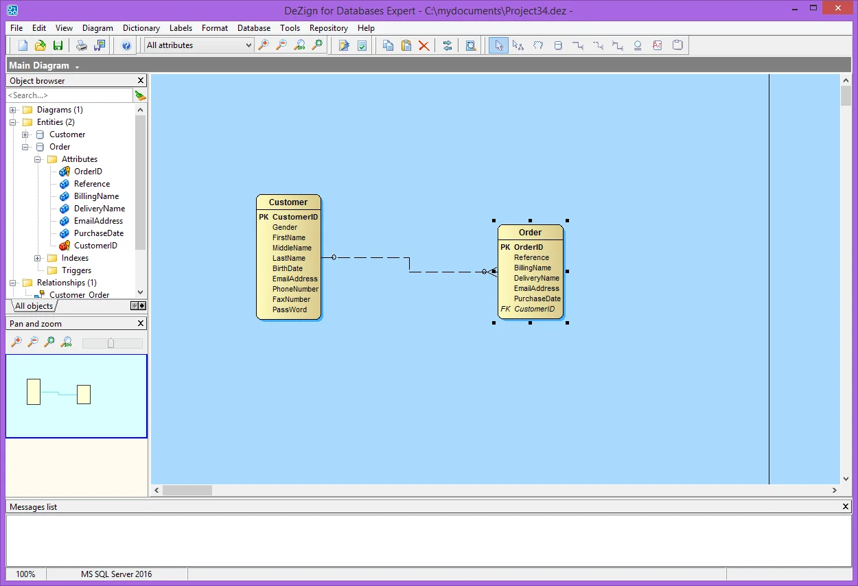
Figure 6: Relationship between Customers and Orders entity (one-to-many relationship).
Using Domains
Domains are reusable user-defined types or "attribute templates" that promote consistent attribute definitions. You construct domains as you would attributes, specifying a name, data type properties, default values and validation rules. Afterwards, you can reuse them in your data model by applying them to attributes.
In our example we have 4 address attributes. We want them to be all of the same type and length. To make sure this will always be that way we create a domain.
To add a new domain select Dictionary | Domains and click the Add domain button (shortcut: Ctrl-Insert) in the Domains dialog. We type the name AddressLine in the Domain name column, choose VARCHAR2 as the data type and set the length (below on the General tab of the properties) to 50. Now click OK. We created a domain now.
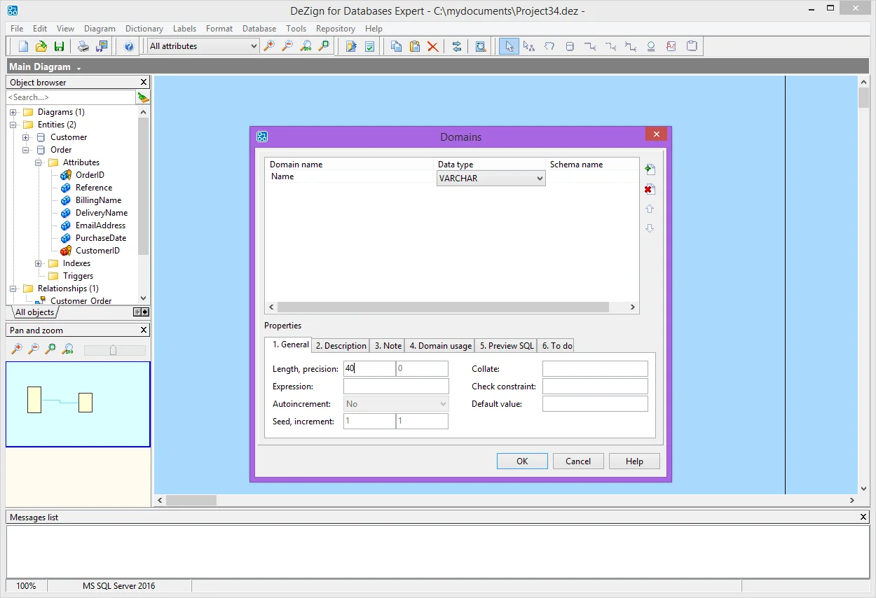
Figure 7: Add, edit and delete domains in the Domains dialog.
You can associate the domain with attributes at this point. Open the Edit entity dialog for entity Customers (double click on the Customers entity in the diagram window). Change the data type of Address1 and Address2 to @AddressLine. (@AddressLine is the domain we just created. Domains will be added to the list of data types.) Do the same for ShipAddress1 and ShipAddress2 of the Orders entity. Now if it appears in the future that VARCHAR2(50) is too short, we can change all Address attributes by changing the length of the AddressLine domain.
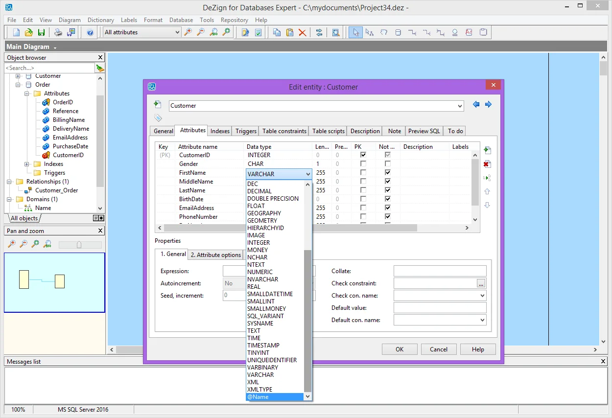
Figure 8: Selecting a domain for an attribute.
Generating a New Database
We can now generate a database from the model. For SQL database, DeZign for Databases will generate a SQL create file and a SQL drop file. For desktop databases such as MS Access, DeZign for Databases will generate the database directly.
Select Database | Generate database (shortcut: F9). The Generate database dialog will appear. For SQL databases you have to define the name of the SQL file to be generated. For desktop databases you have to define a database name or a directory. Click Generate.
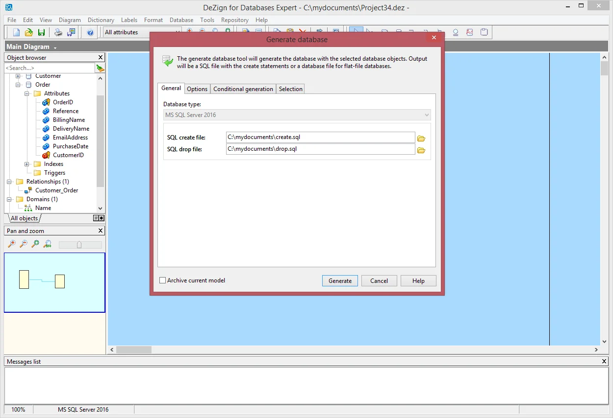
Figure 9: Generating the database.
After generation is complete, the list of generated files will be shown. Select the create.sql file and press the View button. The create.sql file will be opened in the program that is associated with .sql files on your computer. Now you need to open a tool to execute the sql script and run the script on the database. After executing the script the model is implemented on the database.
| Note: In the Professional and Expert edition, a version/snapshot of your model will be created for the generated database. This enables you to generate an alter script with all changes made in the model after this moment. You can find all versions of your model in the Versions dialog (File | Versions). |
Synchronizing Your Model With the Database
DeZign for Databases' synchronization features help you easily compare and synchronize changes between a data model and its related database.
1. Update Model Changes to Your Database
The database can be updated with changes made in the database model by generating an alter script. We will first make changes to the database model and synchronize the changes to the database created before. Let's say we want to add an Orderstatus to the Orders. We add an entity OrderStatus with attributes:
- StatusID, INTEGER, PK.
- StatusName, VARCHAR2(50), Not null.
Next we add a non-identifying, one-to-many relationship with Orders at the many side. This added an attribute StatusID to the Orders entity as foreign key attribute. Now we can generate the alter script to apply the changes to the database.
Select Database | Alter database. In the Alter database from version field you will see "Version yyyy-mm-dd" which is the version that was stored when we first generated the database. In the To version field you see [ current version ] which is the version we are working on. By clicking on the Differences button you can view the differences between the from and to versions.
After reviewing the differences you can generate an Alter script by pressing the Generate button. DeZign for Databases will generate a SQL file (for SQL databases) with the script to alter the database. After generation is complete a list with the sql file and log file will be shown. Select the alter.sql file and press the View button. Open a tool to execute the alter.sql file on the database. After executing the script the changes are implemented on the database.
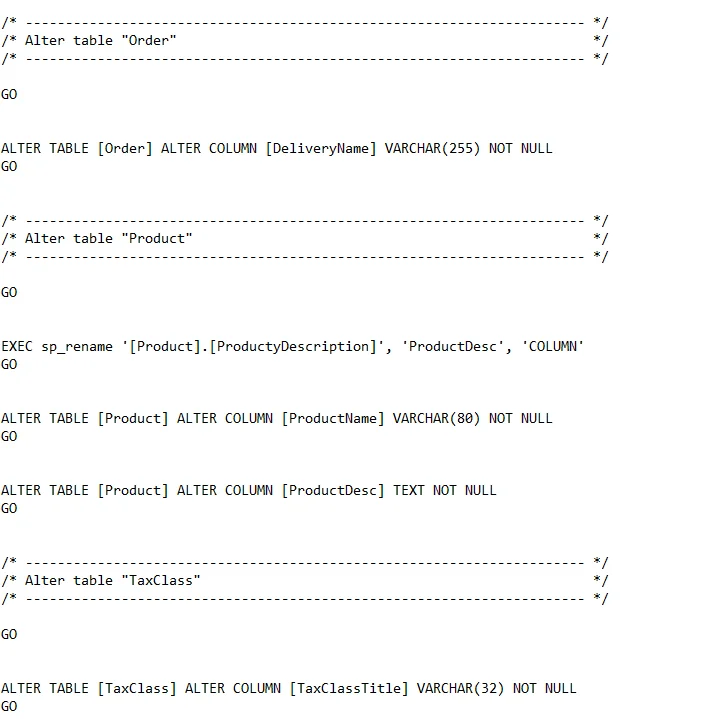
Figure 10: Script generated after changing the database model.
2. Update Your Model From the Database
Changes can be made to the database in many ways. How do we know that our model is still the same as the database? You can update your model by connecting to the database.
Let's add a table to the database using an external tool. We add a table Employees with attributes:
- EmployeeID, VARCHAR2(10), PK.
- Gender, VARCHAR2(1), Not null.
- BirthDate, Date.
- FirstName, VARCHAR2(50), Not null.
- LastName, VARCHAR2(50), Not null.
We also add a column EmployeeID to the Orders table in the database and a foreign key constraint Employees_Orders.
Now we return to DeZign for Databases and will update the model. Select File | Update model from database. Enter the connection parameters in the Update model from database dialog and enter the schema/owner that you used to create and alter the database. DeZign for Databases will read the database and display the differences between your model and the database (see Figure 10). After pressing OK the changes will be merged into the data model.
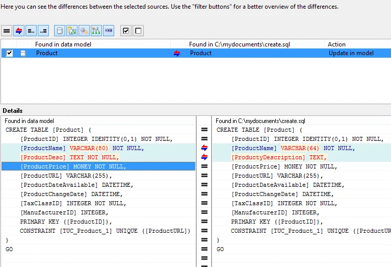
Figure 11: Differences found between the database and the model.
Generating Documentation
The data model may be useful information for other persons involved in application management, functional analysis, application development etc. From our model we can generate the necessary documentation. DeZign for Databases can generate the documentation in several formats: HTML, PDF or MS Word. In this example we choose to generate documentation in the HTML format.
Select File | Reports | HTML report. In the Generate HTML report dialog you can choose between a Logical and Physical model report. We choose the Physical model report. The Physical model report includes more information related to the physical database like data types and constraints and uses the physical definitions like table (entity) and column (attribute).
Next select a directory to save the html files to and press the Generate report button. A Resize image dialog is shown where you can choose to resize the diagram. After the report has been generated you get a message where you can choose to view the report. DeZign for Databases will open the report in your default browser (see Figure 11).
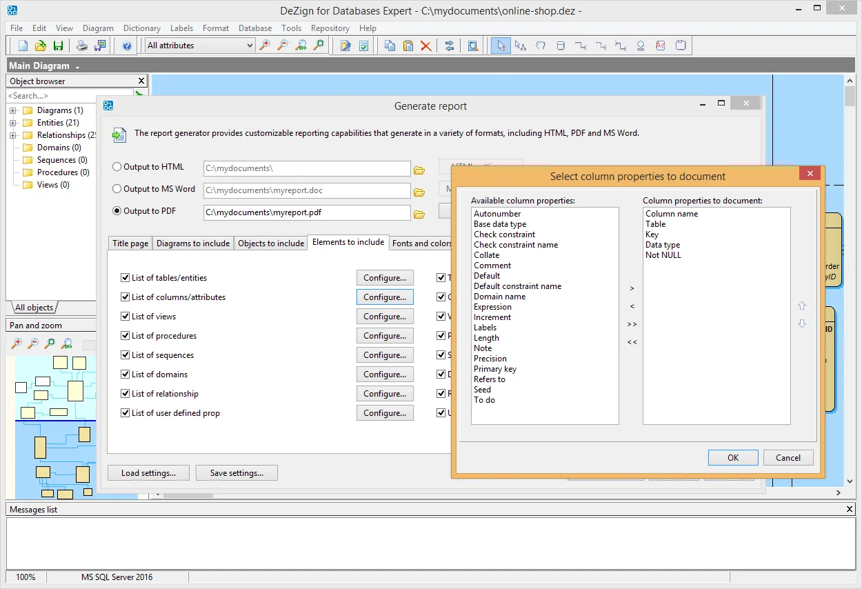
Figure 12: Generate database documentation.
Adapting Diagram Presentation
Depending on the situation you may prefer different information to be displayed in the ER diagram. You can change the level of details that are displayed.
Select Diagram | Data type display level | Names with physical data type or domain. Now you see for each attribute the data type with length in the diagram.
Suppose we want to see a description of the relationship. We open the properties of the relationship Customers_Orders by double-clicking it. Enter "placed by customer" in the Inverse phrase. Next, select Diagram | Relationship caption style | Parent and child phrase and you see "placed by customer" on the Orders side of the relationship.
There are several other options in the Diagram menu to influence the information shown in the ER diagram. Next to which information is shown you can change where certain information is shown via File | Display preferences.
Another way to customize your diagram is by using colors (see also: Brighten up your data model diagrams: give them color). To indicate that the CustomerID attribute in the Orders entity is linked to the CustomerID attribute of the Customers entity we give them the same color. Right-click the Customers entity and select Format | Attribute color settings. Select the attribute CustomerID and pick a color. Now do the same for the CustomerID attribute in the Orders entity and pick the same color.
Resources
Learn- DeZign for Databases: Learn more about DeZign for Databases.
- Display data types in a diagram: Learn how to display data type and/or domain info in the entity boxes on your diagram.
- Build your next data model with DeZign for Databases trial software, available for download directly from Datanamic's download section.